
Photo by the Arduino Robot official website
In this article, I would like to explain a basic understanding of the Arduino Robot.
1. Hardware composition
The Arduino Robot is composed of two boards and two wheels.
The upper board is the Control Board, the lower board is the Motor Board.

2. I/O equipment
The Control Board and the Motor Board has some I/O equipment as follows.

Control Board I/O equipment
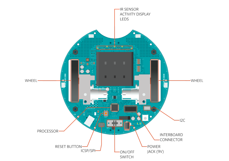
Motor Board I/O equipment
3. Control Board I/O Pins
Control Board has some pins as follows.

Control Board TK/TKD pins
・TK0 to TK7 pins
TK pins are used as analog input for sensors, like distance sensors, analog ultrasound sensors.
・TKD0 to TKD5 pins
TKD pins are used as digital I/O. A HIGH or a LOW voltage value can read/write through pins.
4. Motor Board I/O Pins
Motor Board has some pins as follows.

Motor Board B_TK pins
・B_TK1 to B_TK4 pins
B_TK pins are used as analog/digital inputs.
A HIGH or a LOW voltage value can read/write through pins.
For now, I just want to know these TK/TKD/B_TK pins play a role in analog/digital I/O pins.
I'll describe later about the details of these pins.
5. For more details about the Arduino Robot
The Arduino Robot has some other features. If you want to know these details, please refer to the Arduino official website.
In this article, I explained a basic understanding of the Arduino Robot. I would like to explain how to try some samples of the Arduino Robot in the next article.
No comments:
Post a Comment